Written by Krey Price | Surface Water Solutions
Copyright © The RAS Solution 2019. All rights reserved.
Copyright © The RAS Solution 2019. All rights reserved.
Using RAS Mapper as a GIS tool Part 3:
Georeferencing hard copy or pdf maps
Georeferencing hard copy or pdf maps
Have you ever received your background data in hard copy or pdf format and wanted to view it in its georeferenced location? For this final topic in our three-part series on using RAS Mapper as a GIS tool, we'll cover the steps required to georeference a map using world files. [For additional background see the previous posts Part 1: Terrain modification and Part 2: Web imagery with world files.]
Before you begin any georeferencing process, always check that you are using the correct projection (and confirm the desired projection with the client or end user of the data.) If you don't know which projection to use, you may need to check with the provider of your LiDAR data or other geospatial data. If your terrain file has been provided in geotif format, another option is to add the terrain file to RAS Mapper without assigning a projection, then double click on the name of the terrain, select the "Source Files" tab, and click on the "Info" button to view the GDAL metadata. The projection should show up under the "PROJCS" tag:

If you don't have the relevant projection file available, most projections (with the exception of local project grids) are available online for free download. Projections are typically catalogued according to European Petroleum Survey Group (EPSG) codes maintained by the International Association of Oil and Gas Producers. [When you think about it, it makes sense that the oil and gas industry would have a substantial interest in pinpointing global locations for exploratory wells and other critical geospatial data!]
Online repositories for projection files such as spatialreference.org include the EPSG code with each spatial reference system:
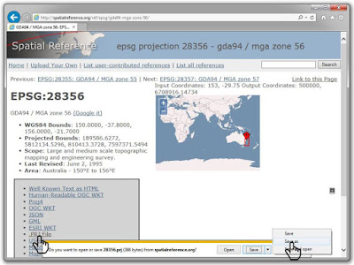
Projection files can also be copied from the prj file associated with any shape file that matches the target coordinate system. In any case, once I've got the correct prj files, I like to place it in a separate subfolder named "projection" that I create under my project directory, and then assign it a file name such as "GDA 94 MGA Zone 55 Projection.prj" that clearly distinguishes it is a projection file (as opposed to a HEC-RAS project prj file!) I also like to make sure that the projection folder includes only a single prj file so that anyone who picks up the project in the future knows the intended projection. [RAS Mapper sometimes loses the spatial reference system association and that can avoid confusion when it is re-assigned.]
Once you've confirmed that you are using the correct projection (typically by turning on web imagery and checking that it lines up with your terrain, shape files, or other geospatial data for your project) you can georeference any hard copy, scans, image files, or pdf files within the specified projection.
The georeferencing steps are covered on our new YouTube channel in this video walk-through beginning at 6:37:

1. For hard copies, scan your image to a raster format (commonly jpg or tif). For pdf files, use "save as" in Adobe Acrobat and select jpg (resolution can be adjusted under settings). For other file types, you may wish to use the Snipping tool that ships with Windows and save the screenshot as a jpg (best if it's on a high-resolution screen as you'll be stuck with the screen resolution and not the original source file's resolution).
2. Create a new file in Word, Notepad, Wordpad, or other text editor or word processor (or copy an existing world file and skip to Step #5).
3. Enter six lines of numerical text. Use dummy values from "original world file" column in the World File Calculator spreadsheet (available for free downloaded here) or take an initial guess at values based on the assumed coordinates of the upper left pixel.
4. Save file as plain text format (*.txt) using the same file name as the image file (select "default settings" if prompted).
5. Change file extension in Windows Explorer to *.tfw, *.jgw, *.bpw, etc. as appropriate to match your image file format (click yes if prompted with unusable file warning).

6. Under Map Layers in RAS Mapper, right-click and select "Add Existing Layer". Be sure to drag down file types to show all image files. Browse to file and select OK.
7. Using the measure tool in RAS Mapper, measure the distance between two points that are a known distance apart (preferably from a scale bar or coordinate tick marks on the map).
8. Open the World File Calculator spreadsheet (or create your own - there's really not that much to it!) and enter the measured and actual distances under Line #1 (cells D3 and E3) and again in Line #4 (cells D6 and E6).
9. Copy values from "New World File" column, open the world file in a text editor, and paste the updated values over the old values.
10. Right click on the image file and select "remove layer".
11. Re-add the image file and adjust transparency as needed.
12. Using the measure tool in RAS Mapper, click on a known point from the original image (with incorrect location), then double-click on the same known point based on the correct location.
13. Select "Copy coordinates to clipboard".
14. Paste the coordinates into Cell C10 in the spreadsheet (Note: values will be replaced in the cell range C10:F12 but only C10:D11 are used in the spreadsheet).
15. Copy "New World File" column over the previous values in the world file.
15. Remove and re-add the image file under map layers in RAS Mapper.
16. Adjust transparency as needed to confirm common points are now co-located. Measure the scale bar to confirm correct scaling.
3. Enter six lines of numerical text. Use dummy values from "original world file" column in the World File Calculator spreadsheet (available for free downloaded here) or take an initial guess at values based on the assumed coordinates of the upper left pixel.
4. Save file as plain text format (*.txt) using the same file name as the image file (select "default settings" if prompted).
5. Change file extension in Windows Explorer to *.tfw, *.jgw, *.bpw, etc. as appropriate to match your image file format (click yes if prompted with unusable file warning).

6. Under Map Layers in RAS Mapper, right-click and select "Add Existing Layer". Be sure to drag down file types to show all image files. Browse to file and select OK.
7. Using the measure tool in RAS Mapper, measure the distance between two points that are a known distance apart (preferably from a scale bar or coordinate tick marks on the map).
8. Open the World File Calculator spreadsheet (or create your own - there's really not that much to it!) and enter the measured and actual distances under Line #1 (cells D3 and E3) and again in Line #4 (cells D6 and E6).
9. Copy values from "New World File" column, open the world file in a text editor, and paste the updated values over the old values.
10. Right click on the image file and select "remove layer".
11. Re-add the image file and adjust transparency as needed.
12. Using the measure tool in RAS Mapper, click on a known point from the original image (with incorrect location), then double-click on the same known point based on the correct location.
13. Select "Copy coordinates to clipboard".
14. Paste the coordinates into Cell C10 in the spreadsheet (Note: values will be replaced in the cell range C10:F12 but only C10:D11 are used in the spreadsheet).
15. Copy "New World File" column over the previous values in the world file.
15. Remove and re-add the image file under map layers in RAS Mapper.
16. Adjust transparency as needed to confirm common points are now co-located. Measure the scale bar to confirm correct scaling.
Hopefully the first try will get you close enough for your purposes, but the process can be repeated to fine-tune the results as needed. You can also use these steps to convert geospatial data to or from a local project grid for which projection details are unavailable.
Keep in mind that these adjustments only provide a visual approximation and should be treated cautiously if the results are to be used for permitting or construction purposes. In that case, you'd want to get a surveyor on board with the proper tools to apply all of the required warping factors and address any other discrepancies.
The full set of parameters in a projection file can get quite complex; projecting a curved surface to a flat plane comes with mathematical difficulties that have plagued mapmakers for centuries. Here's a great video explaining why all world maps are wrong.

With these difficulties in mind, it is no surprise that even if you get two points to line up perfectly, a third point can still be shifted, particularly for points located a significant distance away from the alignment points. For manual georeferencing, I suggest using alignment points that are as far apart as possible for your selected zoom extent to avoid major discrepancies.

Although rotation terms can be added to the world file by measuring the angular difference between lines drawn between two known points, my preference is to make rotation adjustments graphically before diving into any world file adjustments. Raster images can be rotated in a number of programs (Photoshop, Paintshop, Word, PowerPoint, etc.) to achieve a proper north alignment. [The "Z axis rotation" can be used in Microsoft products to apply specific sub-degree rotation factors.] The rotation terms can then remain as zero values in the world file.
We hope you have found this useful for your work. Please let us know if you have any comments or suggestions for improving these processes! Thanks for tuning in, and as always, let us know your recommendations for upcoming blog topics.
Collecting ideas for future posts: One subject we are working on for a future post is hacks for removing flow from HEC-RAS models. Internal boundary conditions are very useful for adding flow anywhere in your model, but removing flow can be a tedious process requiring a bit of creativity. Some new features coming in Version 5.1 may simplify the process, but in the meantime I've seen some clever workarounds being applied that we would like to share with this forum; please contact me if you have done this successfully so we can perhaps feature your method in an upcoming blog post.
With these difficulties in mind, it is no surprise that even if you get two points to line up perfectly, a third point can still be shifted, particularly for points located a significant distance away from the alignment points. For manual georeferencing, I suggest using alignment points that are as far apart as possible for your selected zoom extent to avoid major discrepancies.
Note on rotation factors: The above steps assume that north is straight up in your hard copy or pdf map based on the applied projection (or at least close enough to straight up to suit your purposes). If not, rotation terms can be added to the world file, but in my experience this can lead to some confusion, as the pixels shift on the fly at different zoom levels.
Although rotation terms can be added to the world file by measuring the angular difference between lines drawn between two known points, my preference is to make rotation adjustments graphically before diving into any world file adjustments. Raster images can be rotated in a number of programs (Photoshop, Paintshop, Word, PowerPoint, etc.) to achieve a proper north alignment. [The "Z axis rotation" can be used in Microsoft products to apply specific sub-degree rotation factors.] The rotation terms can then remain as zero values in the world file.
We hope you have found this useful for your work. Please let us know if you have any comments or suggestions for improving these processes! Thanks for tuning in, and as always, let us know your recommendations for upcoming blog topics.
Collecting ideas for future posts: One subject we are working on for a future post is hacks for removing flow from HEC-RAS models. Internal boundary conditions are very useful for adding flow anywhere in your model, but removing flow can be a tedious process requiring a bit of creativity. Some new features coming in Version 5.1 may simplify the process, but in the meantime I've seen some clever workarounds being applied that we would like to share with this forum; please contact me if you have done this successfully so we can perhaps feature your method in an upcoming blog post.
And speaking of Version 5.1, right at the top of my wish list for HEC-RAS updates is for project files to be called *.ras files, *.hrp (HEC-RAS Project) files or any unique extension that doesn't happen to coincide with thousands of other files on my computer (in this case, of course the ESRI-format *.prj projection files). I understand the Corps may have been first in this case (calling their project files prj's well before ESRI did) but the rest of the geospatial industry is not about to change their format, so maybe HEC-RAS project files can get a unique identity in the next version - or at least a search tool within RAS that can recognize and distinguish HEC-RAS-format project files. Let us know if you agree and maybe we can turn this into a grass roots, crowd-based request!