
Written by Daniel Christensen, P.E. WEST Consultants
Copyright © RASModel.com. 2013. All rights reserved.


Copyright © RASModel.com. 2013. All rights reserved.
Our office ran into an unusual modeling situation recently. Here is a description of the situation: The project is a dam breach model, and the spillway for the dam diverts water to an adjacent basin. The spillway is actually more like a canal (the spillway reach) that runs about a mile until it empties into the adjacent basin. The dam that impounds the main creek has a typical regulating outlet system that supplies water to the main creek, while the adjacent creek (supplied by the spillway) remains dry except for large flood events when the pool rises above the invert of the spillway. The original unsteady model was constructed such that the creeks were modeled as separate reaches, both connected to a storage area representing the reservoir (see FIGURE 1 below). Both the dam and spillway were modeled as an inline structures. FIGURE 2 shows a close-up view of the spillway.

FIGURE 1

FIGURE 2
The problem we were presented with was: "How do we handle the dry-bed situation in the adjacent creek when the pool elevation in the reservoir is below the invert of the spillway?" The starting reservoir elevation for the PMF/Flood Scenario dam breach was actually 20 ft below the spillway’s invert. If you tried to the run the model with a boundary condition that was 20 feet below the main stream bed, the spillway reach would immediately go "dry" causing the model to crash (see FIGURE 3).
We had to get a little creative to resolve the dry-bed issue while still maintaining an accurate replication of the true geometry. Instead of connecting the spillway reach to the reservoir storage area, we disconnected it and assigned a constant, low base flow to the spillway reach as an inflow boundary condition (100 cfs. We knew the max flow for the spillway was 20,000 cfs so 100 cfs wouldn’t make a difference in the max stage in the creek). This simple change fixed the dry bed issue in the spillway reach. But we still need to provide a connection from the reservoir to the spillway reach, using the spillway crest as the hydraulic control.
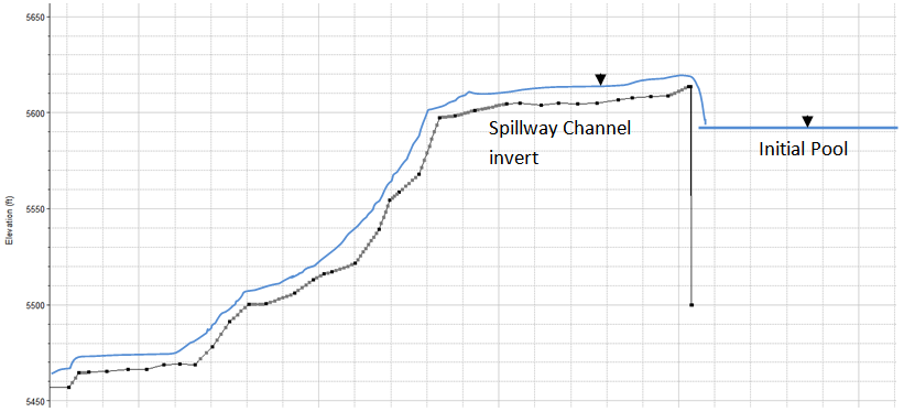
FIGURE 3
To connect the storage area to the adjacent creek, we defined a lateral structure on the left bank that was 2 or 3 cross sections downstream from the top of the reach (see FIGURE 4). The reservoir was defined as the lateral structure’s tailwater, and the spillway crest was used to define its weir embankment. The weir coefficient was tested for multiple runs until the flow out of the lateral structure matched the spillway rating curve. A final weir coefficient of 1.2 was used. Also, to prevent the base flow (100 cfs) from flowing back into the reservoir when the pool elevation was lower than the spillway crest, “Flaps to prevent Positive Flow” were assigned to the lateral structure. Keep in mind, positive flow is defined as the flow from the main channel that the lateral structure is associated with, to the tailwater (in our case, the spillway reach to the reservoir). Therefore we only wanted to see "negative" flow. Even though there were no "flap gates" in the spillway, using the "Flaps to prevent Positive Flow" feature, prevents any flow from going from the main channel to the storage area.

FIGURE 4