
One current limitation in HEC-RAS 5 is that when you put a culvert or gate in a 2D Area Connection, flow through the culvert or gate can only go from a cell adjacent to the 2D Area Connection line on the upstream side to a cell adjacent to the 2D Area Connection on the downstream side. If your cell size is relatively small and your culvert is relatively long, then your culvert may in reality span many cells between its upstream side and downstream side. But the current limitation doesn't allow this.
 But we're in luck! Mr. Con Katsoulas, a senior water resources engineering from SMEC in Sydney Australia came up with a method to get around this limitation. He first discussed this in The RAS Solution forum. And my friend and colleague, Mr. Krey Price of Surface Water Solutions wrote a detailed explanation on how to use this technique. Please read his blog post on wormhole culverts for the full description.
 Good luck! Give it a try and let me know how it works for you.
this is really great ]
ReplyDeleteWow, what a clever and useful idea! Thanks for sharing, Con (and Chris)! I'd love to about the accuracy of this method, beyond its brute functionality in moving water from Point A to B. Hopefully, a few people with calibrated 1D bridge/culvert models can try this out and share their findings.
ReplyDeleteIf you're interested in more details, the May 16 2017 post on the blog presents a comparison of the wormhole culvert hydraulics against 1D bridge/culvert models, and the May 23 2017 post presents a comparison of upstream and downstream hydrographs to check the hydrological effects of wormhole culverts.
DeleteI was able to make the long culvert work (still testing to see how effective it is for my situation), but I was very curious about utilizing this method to add internal boundary conditions for inflows. I didn't quite understand how you were able to make that work. I have used the "PAC-MAN" method before and it seems like I always have flow that needs to cross that PAC-MAN border.
ReplyDeleteWhen you say you introduced an "artificial upstream storage area" are you referring to simple DEM manipulation to contain the inflow in this artificial storage area just inside the 2D model boundary and then utilizing your snake method to route your hydrograph to the desired point of internal inflow?
Any clarification would be welcome. It is a wonderful idea on how to deal with the limitations of the model and was a well written piece. Thanks for the insight.
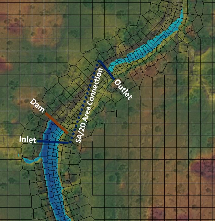
Thanks for your query. I posted an additional example at http://www.surfacewater.biz/wormhole/ showing a case where flow has been moved from an artificial storage area (a fake reservoir) to another tributary. The artificial storage area is just anywhere within my 2D Area where I choose to store water for use elsewhere. As long as it doesn't interfere with the rest of my model, I can just put a dam around it (using the SA/2D Area Conn with a raised weir embankment), adjust the inflow to fill it up, and make a reservoir that I can draw on to route the flow anywhere else within the model using a wormhole culvert. A bit cumbersome (and hopefully won't be required as a workaround in future HEC-RAS releases) but for now it seems to do the trick. By the way, the example also shows the Pac-Man method...in case that designation isn't as self-explanatory as I might think as a retro fan. :)
ReplyDeleteChris-
ReplyDeleteI have a hopefully simple question related to lateral structures in a simple steady-flow 1-D HEC-RAS model (although I'd also be curious if the same rule applies to a 2-D model).
Is it possible to connect a lateral structure from one reach so that it discharges to the most upstream cross section of another reach? Or must the discharge point always be "between" two cross sections on the "receiving" reach?
Right now it appears to me that the discharge point must always be between two cross sections.
Thanks for any explanation you can provide.
Yes. You are correct. It has to go between two cross sections.
DeleteMy question is little different from the topics. I have two pumps in my unsteady RAS model. The head difference between"pump from" and "pump to" stations is consistently not less than 8ft. However, my model is using flow rate for only 0ft head from pump efficiency curve. Can you tell what might cause this?
ReplyDeleteNot sure.
DeleteVery cool! Thanks for the workaround!
ReplyDeleteI've been using these wormhole culverts for a model and posted some observations in the forum. Would be interested in other's thoughts.
ReplyDeletehttp://hec-ras-help.1091112.n5.nabble.com/Wormhole-Culverts-Discussion-and-Observations-tp3913.html
Howdy folks! I'd encourage you to revisit Jennifer's thread and see if you can help contribute to working knowledge of wormhole culvert modeling. There have been a few great contributions here that you might be able to draw knowledge from.
DeleteI've also posted one of my own challenges that you might be able to help me think through.
http://hec-ras-help.1091112.n5.nabble.com/Wormhole-Culverts-Discussion-and-Observations-tp3913.html
Hi! I have a project where I have to build a wall surrounding the property. I use a breakline to represent the wall in a 2D model. I need to use the culvert across the property to prevent the water from being trapped by the wall of the property on the upstream. My question is how can I apply this wormhole culvert in my model given that the property is surrounded by breakline which is a perimeter wall?
ReplyDeleteIs there a way to show how much flow goes through the culvert only? I have a model and there is a substantial amount of overland flow in addition to the flow through the culvert. I want to capture just flow through the culvert.
ReplyDeleteWhat about the detailed output table? It should show what only goes through the culvert(s).
DeleteIs there a way to pull the flow results for just the culvert? My project has a lot of flow so water spills through the culvert and also overland, across the weir. I want to capture just flow in the culvert. Is there a way to do this?
ReplyDeleteHi Chris & Krey, I know that pump is not available for 2D yet but can we mimic pump with a 2D connection by defining an outlet rating curve?
ReplyDeleteAs long as you can make a rating curve that replicates the pump and how it operates, yes you can use that as a 2D area outflow boundary condition.
DeleteHi Chris, Hi Krey.
ReplyDeleteIs it possible to show low flow profile inside a culvert when I have a full 2D model? In a Hydro-Flattened DEM (without the deck of the bridges) this is possible but in non-Hydro-Flattened DEM, in the profile result (RAS Mapper), I see only the water upstream and downstream of the bridge/culvert.
Thank you in advance for the answer.
Andrea
Not currently (5.0.6), but I hope they add that soon. For now, if you want to see a water surface profile through a culvert, you have to do that in 1D.
Delete-Chris
Hi Chris.
DeleteAnother little question concerning the culverts in 2D Simulation. When I create a ‘Standard 2D Culvert’ over an Hydro-Flattened DEM, there’s like a ‘glass wall’ inside the culvert. This ‘barrier’, which matches to SA/2D Area Connection, is visible in RAS Mapper when I visualize the velocity particles: there’s no continuity between upstream and downstream velocity particles. Is it normal? Thank you in advance.
Andrea
Hi Chris, Hi Krey.
ReplyDeleteAnother little question concerning the culverts in 2D Simulation. When I create a ‘Standard 2D Culvert’ over an Hydro-Flattened DEM, there’s like a ‘glass wall’ inside the culvert. This ‘barrier’, which matches to SA/2D Area Connection, is visible in RAS Mapper when I visualize the velocity particles: there’s no continuity between upstream and downstream velocity particles. Is it normal? Thank you in advance.
Andrea
As long as there is no overtopping/weir flow, the only flow transfer that occurs across the SA/2D Area Connection line will take place inside the culvert. Even if you are using a full 2D model, the culvert will be a 1D element within that model, with flow computed based on HDS5 methods. You won't be able to visualize that flow in RAS Mapper because there are technically no gridded elements within the culvert itself (even if you are using the culvert as a proxy for a large bridge structure). As I understand it, the particle tracing in RAS Mapper will show the inflow and outflow taking place at the connecting cells. In a standard culvert, that will be the two cells that touch the intersection of the 2D/SA Area Connection line and the barrel centerline. In a "coordivert" where the barrel centerline is defined by coordinates, the flow transfer will be shown in the grid cells that coincide with the inlet and outlet location. In either case, the 2D/SA Area Connection line would act as a glass wall and the particle tracing would not show any vectors passing through it. As soon as there is overtopping flow, you should see both flow across the connection line as well as inflow/outflow for the culvert (unless it becomes negligible relative to the weir flow).
ReplyDelete