
Copyright © The RAS Solution 2016. All rights reserved.
HEC-RAS has the ability to simulate flow at hydraulic
controls in a variety of ways.

 (1)
(1)
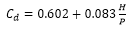
Where:
Q = discharge, C =weir coefficient, L = weir crest length, H = Energy
head over the weir crest.
But each of the three cases apply the weir equation slightly
differently.
Before I continue, I should discuss the
difference between the weir coefficient and the discharge coefficient. I see both of them used interchangeably, but
they ARE different. The weir coefficient
(as shown above in the weir equation) is a lumped parameter that includes the
discharge coefficient, the gravitational constant, and constants based on
geometric properties.
 (2)
(2)
Where Cd is the discharge
coefficient.
The discharge coefficient
is dimensionless and therefore it is the same in both English (U.S. Customary)
Units and SI Units. The weir
coefficient, since it is a function of the gravitational constant, is not
dimensionless and therefore has different values depending on which unit system
you are using. For example, a weir
coefficient (C) of 3.00 in English Units would be 1.66 in SI units. But both share the same discharge coefficient
(Cd) of 0.56. For convenience, to
convert an English weir coefficient to an equivalent SI weir coefficient,
multiply the English weir coefficient by 0.552.
Be very cautious when considering C
versus Cd. They are different but are
often mistakenly used interchangeably.
In fact, you’ll see the coefficient Cd labeled occasionally in the
HEC-RAS software and literature when discussing weir coefficient.
Ungated Inline Weirs.
When defining inline flow over an “ungated” obstruction
(bridge, culvert embankment, inline structure, SA/2D area connection), you have
two options for computing weir flow:
Broad Crested and Ogee.

Figure 1. Inline structure weir embankment editor.
Both use the same standard weir equation presented above in
equation (1).
The only difference between the Broad
Crested Option and the Ogee Option is that for the Broad Crested option, the
user enters a weir coefficient for C.
For the Ogee option, the user enters a spillway approach height and the
ogee’s design energy head, and HEC-RAS will compute the weir coefficient for
you. This may sound convenient, but as
the name implies, this option should really be used only for ogee-shaped
spillways. And you would have to know
what the design energy head is, a design parameter that is not usually easy to
come by, unless you have the hydraulic design report for the spillway. With both options, submergence reduction of
the discharge is automatically calculated with their own respective methods
(FHWA ,1978 for broad crested, and COE, 1965 for ogee).
Ungated Lateral Weirs.
Lateral weirs are entered in the lateral
structure editor. Inside the lateral
structure’s weir embankment editor, you’ll see two options for weir
computations: Standard Weir Eqn. and
Hager’s Eqn.

Figure 2. Lateral
Weir Embankment Editor.
In version 5.0.1, the Standard Weir Eqn.
provides four options for the weir crest shape:
Broad Crested, Ogee, Sharp Crested, and Zero Height. Caution! Zero Height is NOT used when Standard Weir
Eqn. is selected. This is a bug and
will most likely be fixed for future versions.
If you do select Zero Height and Standard Weir Eqn. together, HEC-RAS
will just use the weir coefficient you provide with the broad crested
methodology. Sharp Crested is not fully
functional in Lateral Structures for version 5.0.1. You’ll notice that no additional input
options (like Rehbock and Kindsvater-Carter, as discussed under the next
section, “Gated Weirs) are available when you select Sharp Crested in the
lateral weir embankment editor. My guess
is that if you select Sharp Crested, it too will default to the broad crested methodology.
Broad Crested and Ogee work the same as
with the ungated inline structures.
With Hager’s Equation, all four weir
crest shapes are available, including the zero-height weir. The same weir equation is used, but an
adjusted weir coefficient is computed based on physical and hydraulic
properties. Each of the four weir types
has its own method for computing the adjusted weir coefficient. There is an input box for “default weir
coefficient”. This is only used for the
first iteration of solving Hager’s Equation.
Since Hager is a function of hydraulic properties, it must be solved in an
iterative fashion. After the first
iteration, the adjusted weir coefficient will be computed and used. Page 8-18 of the Hydraulic reference manual
discusses Hager’s equation and how the adjusted weir coefficient is
computed.
Zero-height weirs are used for cases
where flow will leave a channel laterally, but there is no defined obstruction
or hydraulic control separating the two.
Commonly this is used to simulate flow from a main channel up a
tributary that is being modeled using a lateral structure and a storage or 2D
area. The HEC-RAS 2D manual has a table
of lateral weir coefficients (Table 1).
Table 1. Lateral Weir Coefficients (from the HEC-RAS
2D Manual, page 3-50).

Notice the last category is “non elevated”
overbank terrain. If you wish to use the
weir coefficients in this table to simulate a non-elevated weir, do not use
the Zero-Height weir. That is
strictly for Hager’s equation and Hager’s method automatically computes the
weir coefficient. Instead, use the broad
crested standard equation and enter in the non-elevated weir coefficient
there.
Gated Weirs.
When modeling gated spillways at inline
structures or lateral structures, users can provide a weir coefficient for flow
over the spillway when the gate is completely opened, and out of contact with
the flow (Figure 3). This is different from the discharge coefficient used for
flow over the top of the inline structure (Figure 1).

Figure 3.
Inline Gate Editor
With gated spillways, the user has three
options for the weir shape: Broad
Crested, Sharp Crested, and Ogee (Figure 4).
Broad Crested and Ogee work the same as previously discussed. The Sharp Crested option also uses the
standard weir equation but gives you three options for determining the
discharge coefficient: user-entered,
compute with the Rehbock equation, or compute with the Kindsvater-Carter
equation. For both the Rehbock and
Kinsvater-Carter methods, the weir coefficient will be computed independently
at each time step. So you can have a varying discharge coefficient for varying
heads.

Figure 4. Inline Gate Editor.
The Rehbock equation for the discharge
coefficient was developed for rectangular weirs and is as follows:
 (3)
(3)
Where P = Spillway approach height. This value must be entered to use the Rehbock
equation. HEC-RAS will then compute the
weir coefficient, C using equation (2).
According to Ippen (1950), this equation holds up well for values of H/P
up to 5. And it performs with fair
approximation for H/P values up to 10.
The Kindsvater-Carter method was
developed in English units only and is as follows:
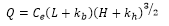 (4)
(4)
Where Ce = effective weir coefficient, ft1/2/s
kb
= a correction factor to obtain effective weir crest length, ft
kh
= a correction factor with a constant value of 0.003 ft
The effective weir coefficient, Ce is a function of two
ratios: L/B and H/P,
Where L = Weir crest length
B = Average width of the approach channel
H = Energy head over the weir crest
P = Spillway approach height
Ce is a function of both the relative width and
relative depth of the approach channel and is taken from the following chart
(note that the chart uses the variable h1 for H. They are the same):

Figure 5. Effective Weir Coefficient
kb is used to determine the
effective length of the weir crest and is a function of the relative width of
the approach channel. It is taken from
the following chart:

Figure 6. Correction factor kb.
To use the Kindsvater-Carter method in
HEC-RAS for a gated spillway, first select the weir shape as “Sharp
Crested”. Then select “Compute with
Kinsvater-Carter eqn as the Weir Method.
You must then choose a relative approach channel width (L/b) and enter
the spillway approach height, P (note, b is used in the HEC-RAS Inline Gate
Editor for B. They are the same).

Figure 7. Kindsvater-Carter Weir Method.
Remember, the Kindsvater-Carter equation
was developed and is presented here in English units. When using SI units, HEC-RAS will
automatically convert the units appropriately.
So you can still enter a spillway approach height in meters if you are
using SI units.
The Kindsvater-Carter weir equation is
built for rectangular weirs and “is particularly useful for installations where
full crest contractions or full end contractions are difficult to
achieve.” (USBR 2001) More information on the Kindsvater-Carter
equation, including its limitations, can be found here: http://www.usbr.gov/tsc/techreferences/mands/wmm/chap07_06.html
References:
Federal Highway Administration (FHWA),
1978. Hydraulics of Bridge Waterways, Hydraulic Design Series No. 1, by
Joseph N. Bradley, U.S. Department of Transportation, Second Edition, revised
March 1978, Washington D.C.
Ippen, A.T. ,1950. Channel Transitions and Controls, Chap. VIII
in Hunter Rouse (editor): Engineering Hydraulics,” John Wiley & Sons, Inc.,
New York. pp.496-588.
Unites State Bureau of Reclamation
(USBR), 2001. Water Measurement Manual, http://www.usbr.gov/tsc/techreferences/mands/wmm/
U.S. Army Corps of Engineers (COE),
1965. Hydraulic Design of Spillways, EM 1110-2-1603, Plate 33.
Can a stepped spillway simulation performed with HEC-RAS?
ReplyDeleteHEC-RAS is not a suitable tool to simulate detailed hydraulics down a stepped spillway. However, to the extent you can simulate the effect of a stepped spillway on the upstream energy head using the equations above, it can certainly be part of a HEC-RAS model.
DeleteHi Chris..........My name is Rodrigo and i am from Chile.
ReplyDeleteI have a question about modelling gated weirs with ogee shape.
The downstream section of the weir is the natural stream section or its located at the end of the ogee profile??
Best regards
Chris
ReplyDeleteIn a ogee crest spilway what is the meaning of the with parameter?
I don't know what the "with" parameter is. Please clarify.
DeleteHi Chris,
ReplyDeleteDo you have any insight into the new "Overflow Computational Method" for lateral structures into a 2d area (e.g. Normal 2D Equation vs. Use Weir Equation)? If one is trying to model a 1d/2d connection where there is overland flow and a non-elevated overbank, what might be the benefits or shortcomings of each method? What would you set your weir width to for an overland flow situation with a low weir coefficient chosen from the table above? Any other advice to reduce 1d/2d flow errors over lateral structures?
Thanks!
Toby-Great questions! the quick answer is: "if it is acting like a weir, model it as a weir, otherwise model it with the 2D equations." However, as with many things in RAS, there's a lot more nuance involved. I like to think about the input data required and how confident I am with it. The weir equation requires a very subjective weir coefficient. The 2D equations do not. Although the 2D equations come with their own subjective assumptions and limitations: terrain quality, theta value, eddy viscosity, full momentum or diffusion wave, etc, etc. So for me, if it's an elevation connection, I'd lean towards the weir. If it is overland flow, I'd lean towards using the 2D equations. HEC does caution against using the 2D equations if the connection is elevated such that water going over it will experience "free fall" (i.e. a waterfall). The 2D equations can't handle that. This might just be another good example where you try them both as part of your sensitivity analysis. Also, keep in mind that the weir width is not used at all in the computations (weir or 2D equations). It is purely there for graphical purposes. As far as advice to reduce 1D/2D flow errors over lateral structures: Break up long lateral structures into multiple smaller ones. Be careful not to use too high of a weir coefficient. Do not have cells adjacent to the lateral structure that reside completely on the slope of the levee/berm/whatever you're modeling with the lateral structure. I typically like to take the cross sections right to the peak of the high ground feature, but start my 2D cells at the toe of the feature. Good luck!
DeleteHello,
ReplyDeleteif you look at the "Storage Area Connection Weir Data", there is a field for input of "Standard Weir Equation parameters". Under this it is written, Weir coefficient (Cd). Now from the explanation Cd(discharge coefficient) whose relationship to C is C=2/3*Cd-(2g)^(0.5) [by the way some books have [C=2/3*Cd-(2/3*g)^(0.5)] which is confusing. have the makers of HEC-RAS made a mistake? did they mean C or Cd?
As mentioned in the post, HEC mistakenly uses Cd in the software occasionally when they actually mean C. All weir coefficients you enter in RAS are the non-dimensionless C values (i.e. they are different for English versus SI units. So be careful with this.
DeleteMy conundrum regards the Weir coefficient in the “Storage Area Connection Weir data”
ReplyDeleteQ1: It is written, Weir coefficient (Cd). Now from your explanation Cd is the Discharge coefficient and C is the weir coefficient. This is very clear. Have the makers of HEC-RAS made a mistake? Did they mean C (Weir coefficient) or Cd (The dimensionless weir coefficient)? You wrote “In fact, you’ll see the coefficient Cd labeled occasionally in the HEC-RAS software and literature when discussing weir coefficient. “. Is this one of these occasions?
The HECRAS reference manual also sometimes refers to C as coefficient of discharge, further compounding the problem.
Q2: You also wrote that C=2/3*Cd-(2g)^(0.5) but some references have [C=2/3*Cd-(2/3*g)^(0.5)] ; This is confusing.
It is as written in the post. The following article does a good job deriving the weir equation if you want verification: http://www.codecogs.com/library/engineering/fluid_mechanics/weirs/discharge.php
DeleteHi Chris,
ReplyDeleteMy name is Ramiro, I work for Hydro-Quebec, Quebec, Canada.
Sorry about my english :)
I'm a little lost on what values to use on modelling a radial gate in a 2D model I'm working on.
I read (HECRAS 5.0 Reference Manual - page 8-8) and I found the equation:
Q=C*(2g)^0.5*W*T^TE*B^BE*H^HE where Q=flow in cfs
I'm using SI units for my model, and in the Connection Gate Editor I need to provide several values for modelling the flow ( Radial discharge coefficient, Trunnion exponent, Openning exponent, Head exponent, Trunnion height) my question is: where I can fin the equation below in SI units and which values to use for those coefficients?)
Thanks a lot!
HEC put that equation in that way to provide more flexibility for how to compute flow through a radial gate. Most people ignore the added terms by putting in 0 for TE, 1 for BE, and 1/2 for HE. I believe they are all unitless, so should be the same for SI and English units. Hope this helps-
DeleteChris
Yes it helps! I calculated (by hand) the flow in both systems (english and SI) with the HEC equation and yes the terms are unitless. Thanks!
DeleteHi Chris,
ReplyDeleteI have a question about what value weir coefficient to use for a SA/2D Connection? I am modeling a 2D mesh into a Storage area and have a SA/2D Connection as a weir set to the elevation of the terrain for the connection?
Thanks,
For 0-height weirs, the weir coefficient should be quite low. Check Table 3-1 on page 3-50 of the 2D HEC-RAS Manual. While these values are presented for lateral structures, I think it will give you an idea of where you should be for your weir coefficient for your situation.
DeleteWhat are thoughts about the option between "compute as curves (faster)" or "compute flow each time step"?
DeleteCompute as curves makes htab tables out of the weir. This is faster, but comes with a little bit of error (potentially). Usually the error is insignificant. Computing flow each time step is a more precise way of getting weir flow, but takes longer, as the software has to recompute the flow each time step. Most likely you won't notice the slowdown.
DeleteHi Chris,
ReplyDeleteEven when working in metric units, when we hover the mouse over Weir Coefficient in the Deck/Roadway Data Editor or Inline Structure Weir Station Elevation Editor, the pop hint still shows the weir coefficient range for broad crested weir as 2.5-3.1 and Ogee 3.1-4.0. Is that a bug? Shouldn't be in the range of 1.3-1.71 for broad crested and 1.71-2.21 for ogee? Thanks.
Yes, that's a bug. I'll let HEC know to fix that. Thanks!
DeleteHi Chris,
ReplyDeleteI'm new to the RAS Solution, so my apologies if this isn't the appropriate spot for this question.
I'm in the process of designing rock weirs, vortex "U" weirs. It appears that HEC-RAS can only model in-line or perpendicular weirs that completely span the creek at one station. Is there a method to accurately model vortex weirs? I really need accurate water surface elevation information for a proposed diversion.
Thanks.
Sounds like a great 2D application. You could make a 2D area in the zone where you have your weirs, then use SA/2D Area connections to simulate your weirs in whatever shape you wish.
DeleteThanks for the quick response, Chris. I am aware of the 2D capabilities of HEC-RAS, but have yet to experiment with them. I'll give it a shot. Thanks again.
DeleteHi Chris,
ReplyDeleteWhen putting a weir in my model, I want to set its crest at critical depth. Is their any way I can see critical depth in the result files? In the result files, I can turn on the critical depths for the x-sections but not for the weir. Is it possible? Thanks.
I'm curious why you want to set your crest to critical depth? Not a critique...just wondering. Why don't you run the model first without the weir, but instead with a cross section in the same location. Get the critical depth elevation from that run, then remove the cross section and replace it with a weir with the elevation of critical depth.
DeleteJust a clarification on seeing critical depth for weirs - this is with relevance to inline structures.
ReplyDeleteI want to place a weir (an inline structure) in my channel (irregular x-section) and I want to make sure that it acts as weir i.e flow passes through critical depth over the weir. I think you can easily put in a weir with crest height so low that it does not effect the flow and the flow does not pass through critical depth. Basically, I am looking for minimum height of the weir that I can use without effecting the water levels upstream.
DeleteTheoretically a weir with any height to it will affect water levels upstream. But why not give it a try. Use progressively shorter weirs until you don't see a significant change.
DeleteHi Chris, Am considering damming a section of a river using a weir to abstract water for domestic supply. Our client is interested to know the effect of building this weir on the upstream side of the river and if there will be any flooding during the max design flood which is 1:100. I was wondering how I can simulate this using HEC-RAS. Our surveyor is going to site soon to do a topo survey of the area. what would be the most important data I could advice he collects for this exercise? Please advice. Thanks
ReplyDeleteHEC-RAS is a great tool for this type of analysis. Based on your question, I assume you are new to HEC-RAS. My advice would be to hire a qualified and experienced HEC-RAS modeler to do this for you. Trust me, it will save you money in the long run and make your client happy. That person would know all of the requirements for setting up and running this analysis. Plus, every site is different, so before recommending what survey data is needed, one needs to know what survey data is already available, it's quality, as well as site-specific conditions that will have an influence on the hydraulics of the system, among many other things. And finally, damming a river with a weir is not a trivial thing. You want to make sure to get it right.
DeleteHi Chris,
DeleteThanks for your feedback. Actually I have used HEC-RAS before but in a class work. Its not really damming the river maybe I used the wrong words, but rather constructing a short weir across the river(2-2.5m high). I was just interested to know what other data I might need for this specific task besides the channel geometry,.
Hi Chris
ReplyDeleteWhen using the 2D connection as a weir embedded in 2D grid, is flow over the weir based on energy level or water level? I'm just cross-checking some HEC 2D results and am trying to resolve some inconsistencies.
Thanks
Craig
Entura
That's a good question. I don't think it is explicitly stated in the manual. I would assume that to be consistent, it uses the energy level. But honestly I don't know for sure. Let us all know if you find out. I'll do the same...
DeleteJust heard back and the answer is RAS uses the water surface elevation as the headwater reference for SA/2D area connection weirs.
DeleteChris, what about user-defined rating curves, such as for a gate in an inline spillway? Does RAS assume you are using Energy Head to define the rating, or Water Surface (hydraulic head)? Examination of results seems to indicate it's using Energy, but what if the gate rating provided (say from a dam operator) is based on WS? I think we'd prefer it use WS rather than Energy, or at least provide an option to switch. Thanks!
DeleteThat would be a nice option!
DeleteI have a small dam that has 2 secondary discharge channel in addition to the primary discharge pipe. The two secondary discharge channels go in two different directions. I am modeling a dam breach and have to had a 1D model through the dam breach, then can switch to 2D for the overland flow through a subdivision that is needed to be mapped. I model the one secondary discharge as a lateral weir leaving the system (and into a 2D flow area) and leave the remaining primary and other secondary discharge as part of the main dam. If the dam were breached the initial secondary discharge would not be part of the breach flows, therefore I need to remove it from the system for the breach. nothing is gated or controlled, it is all gravity. I can get the entire model to work including the 1D unsteady, breach and 2D connections. I have modelled all the weirs as rating curves. Where I am having a problem is that my lateral weir requires that I have a physical weir shown in the model or it will not transfer the flows. However, when I do this, it sets a tailwater elevation that is more than 0.8' higher than the incoming flow elevation. Where this become a problem is that my 2D flow now routes around the dam in a manner that it cannot at the elevations it should be at. This causes additional flow in areas where it should not be. How can I control the tailwater elevation for lateral weirs?
ReplyDeleteI am using 5.0.3. Would also like to see how you can breach a dam in 2D without having to go back to the 1D cross-sections. Guess i'll need to wait for future version...
Thanks for any advice assistance.
Brian
Brian- too much for me to type a response. Why don’t you give me a call at 503-793-2700.
DeleteHi Chris, i'd like to ask you something about radial gates in the inline structure. I have to simulate a weir with three radial gates 10 m x 10 m in steady flow conditions in the case of all the gates opened.
ReplyDeleteWhen i finish the simulation and i look at the inline structure output table i see that the whole discharge is splitted in Qweir and Qgates. I don't understand this thing because i'm simulating a weir with three gates totally opened: in my mind it is like a weir without gates.
Thanks for any advice assistance
Mirko
Even though the gates are fully opened RAS still considers that gate flow. Weir flow would be what’s going over the inline structure.
DeleteHi Chris!
ReplyDeleteI'm Ramiro from Montreal. I work for Hydro Québec.
I have a 2D model and I'm having a problem with conservation of flow.
I have 2 boundaries condition upstream (total flow of 6500 mcs), an inline structure located 5 km downstream and a downstream boundary condition 10 km downstream from there.
The problem I have is I'm losing flow from upstream boundaries conditions to my in line structure, about 7%-10% less flow pass through the in line structure (6000 mcs) . I have the good flow 6500 mcs at the downstream boundary condition. I made 2 geometry files : One with the in line structure with rating curves and another one with 10 radial gates. Both give the same result.
The levels are steady and I have no loses anywhere else.
Do you have any idea how I can improve my simulation?
thanks a lot!
Hello chris! great work on this blog, it helped me a lot during my study. I'm doing a dam break analysis study and I'm having a problem with lateral structures, the model is a combined 1D-2D model where the channel is 1d and both the right and left floodplain are 2d, they're connected with lateral structures. the problem is that the WSE and EG are acting weird and doing these little steps in various locations in my reach https://imgur.com/4QXcugl and these are the only places where the water overflows from the river to the floodplain. I've tried: using very small timesteps (from 0.5s to 10s ), increasing HTAB points, small cross section spacing(15m). if you have any tips or hints that can help it would be greatly appreciated.
ReplyDeletethank you
Ali
Hi Chris! I'd like to ask you about conservation of flow in a 2D model.
ReplyDeleteI have a model with 2 boudaries upstream with an constant flow going into the model, a dam with 10 radial gates in the middle and 1 boundary condition downstream. The proble I have is I'm losing 7% of flow:
Upstream flow: 6500 mcs, fow through the dam 6000 mcs, Downstream flow 6500 mcs. Did you hear about this before? Thanks!
Greetings,
ReplyDeleteI am having stability issues while trying to run a steady flow model with a lateral weir. The downstream end of my model is a constrictive rating curve. Then 200 feet upstream of the end of the model is a 100 foot lateral weir overflow with the TW connection set to “out of system”. I am trying to determine the elevation of the channel at various high flows. The weir has a sloped height of 2 to 5 feet. When running the model I get “Flow Optimization Failed to Converge.” I have tried inputting the resulting flows into the “initial split flow optimization” of the steady flow data but that just makes the next results worse. I am getting flows leaving the weir much greater than my steady flow input.
I have tried various weir coefficients ranging from 1.5 - 3.0, with similar optimization failures. Should I go to an even lower coefficient based on the weir geometry? I have tried both the standard weir equation and the Hager’s eqn. Based on my model set up is one method preferable? If I used the standard equation should I have separate geometries with different coefficients for different flows?
I have 50 foot cross section spacing. Is there a place along the channel (above weir, through weir, below weir) where I should have greater or smaller cross section spacing?
Any advice or thoughts would be greatly appreciated!!
Thanks,
Clark
The HECRAS 5.05 version has an option to compute weir coefficient of Ogee weir by supplying Spillway Approach Height and Design Energy head. for example. I supplied 15.98 and 10 respectively and weir coefficient was 2.17. which equation is invoked for calculation?
ReplyDeleteHi,
ReplyDeleteI found two ways to model inline structures (Eg. Broad crested and Ogee weir). One approach would be by creating the broad crested profile with the input of series of cross section while as another approach is to add inline structure on the channel section and define broad crested weir. Would you please inform me which method is more accurate ?
For a spillway, how downstream conditions taken into account? For example for a semi submerged crest...
ReplyDeleteRAS uses a flow reduction factor based on percentage of submergence. You can check the hydraulic reference manual for more detail.
Delete