
Written by Chris Goodell, P.E., D. WRE
Copyright © RASModel.com. 2009. All rights reserved.
Here is an example of a junction.
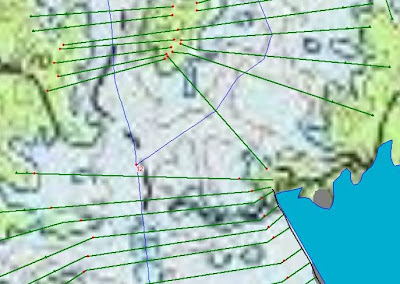 With junctions, generally it is important to get cross sections as close to the junction as possible-even more so with unsteady flow modeling (http://hecrasmodel.blogspot.com/2008/12/unsteady-flow-and-junctions.html).
With this example, I would certainly add more cross sections upstream of the junction like so…
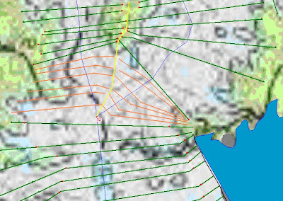
What I’ll usually do is draw an approximate “plane of confluence” (the yellow line), and then butt the new cross sections up to that line, without crossing over it. This plane of confluence will generally follow high ground between the two reaches, but technically should define the boundary between flow lines of one reach and flow lines of the other reach. The new cross sections will be missing the high ground on its “confluence” side, but that’s okay, because the other cross section (in the opposite reach) will capture that.
You certainly do not want cross sections overlapping or extending into another reach’s flow path. Sometimes you’ll find that interpolated cross sections might overlap at times. That’s okay as long as it is just a geometric schematic issue, and that cross sections were not really surveyed overlapped.
Hi Chris,
ReplyDeleteI am currently modeling a dam breach that breaks in a river that has a large slope and then enters a junction where it flattens out. I am having a lot of issues with the water level raising above my cross sections. If I set up my cross sections in HEC GeoRAS as you have them drawn above - will the model know to overtop on the left side of the right river and flow into the left river?
Thank you,
Sarah
Not automatically. RAS will just extend vertical "walls of water" in a cross section where you are above the end points. However, there is no automatic exchange of volume into the adjacent cross section when this happens. If you want to exchange volume from one reach into another, you have to connect them using a lateral structure.
ReplyDeleteWhat do I need to watch out for when digitizing junctions in HECGeo-RAS? As far as, do my flow paths, banks, rivers need to intersect, and where?
ReplyDeleteYour reaches should snap together at the junction. Each junction needs to have 3 or more discrete polylines representing reaches that come together at a single point.
ReplyDeleteFlow paths should terminate after intersection the downstream most cross section on the tributary reach. The primary river can have flow lines that project through the junction and are continuous from the upper reach to the lower reach. If they dont, that is okay too. Just be aware that the downstream cross section in the upper reach of the primary river will have 0 (zero) for its reach lengths-which is okay-they're not used anyway.
Bank stations can be continuous through the junction. Just make sure they don't intersect flowlines and they only intersect any given cross section once.
Hi Chris.
ReplyDeleteHow can I enter the lenght between the junction and the downstream cross section?
For now, RAS assume the same lenght between the primary river cross section and the juntion.
Keep up with this blog, it's amazing!
Rodolfo Dornelas.
For computations in RAS, the legnth from the junction to the downstream cross section (and the length from the upstream cross section to the junction are irrelavant. You only need to enter the length over the junction from the upstream cross section to the downstream cross section.
ReplyDeleteHowever, if you want your cross sections and junctions to look spatially correct in the geometry schematic, then you can provide coordinates to the cross section cutlines, either manually, or by using GeoRAS.
Chris, in the example above I typically put in a lateral weir(s) to help transfer flow in the overbank across the junction. You see any issues doing this? I set the weir coefficient low (0.5 to 1.2) paying attention to continuity of flow in the overbank vs. flow across the weir(s).
ReplyDeleteLA
It is interesting your method. Please explain how to put lateral weirs?
DeleteChris, In my model upstream reach, has been divided to two reaches left and Right at downstream, reach right is going to through a lock that is every time close in the model and reach Left starts with a Dam. when am I looking at the profiles, the main reach profile at upstream is followed(getting effective) from just Right reach, why? why not the other reach?
Delete1-How much is the flow data at the junction for two new reaches(upstream flow is 37cms)?
2-the lock is close but I see flow in downstream of lock at the model
3-what is the best approach to modeling a side navigation channel on the rivers?
Thank
M.A
LA, that's an interesting approach, and one I haven't thought of before. Sounds like it would work, and good that you're tracking flow continuity (especially given the uncertainties with weir coefficients). Other than it might look "odd" to your client, I don't see any issues with it in principle. If you have time, can you write post showing how you do this? I'll post it up here on the blog.
ReplyDeleteWhat do you mean by flow continuity? Does this mean you shouldn't have more flow over the weir than you have in the overbank?
DeleteThanks Chris, I will do.
DeleteHas an example on the lateral weir to join two reaches been posted?
DeleteYou might check the HEC-RAS applications guide and/or the sample data sets that come with HEC-RAS. You'll likely find something like that there.
DeleteThanks so much, I've reviewed these and was hoping you could give me some advice. I'm modeling an off-channel raw water reservoir that is pumped to from the river. I need to model a break in the dike on the north side and out to the river which is not directly on a channel. My model is crashing and I'm wondering what the best way to model the situation is. I've attached a drawing showing the layout for your reference in the link below. The tributary to the west is lower than the floodplain to the north and east of the reservoir and I believe this along with the reservoir not discharging to a channel is causing instability. Do you have any recommendations on how best to model this situation?
Deletehttps://drive.google.com/open?d=0B6_4IH__UEn9S3FMTUNSbldHakE
Hello Chris,
ReplyDeleteI have imported a stream and tributary from InRoads but they did not intersect, so I do not have a junction.
I editing the tributary reach to make them intersect (moved the last point) but the junction has not been recognised.
Is there a way of making HECRAS recognise the junction, or do I have to edit the streams in InRoads and reimport them?
Cheers
I've now solved the junction problem - was doing 2 things wrongly.
ReplyDelete1 - The way you label rivers/reaches
a) A river splits into reaches
b) A tributary must be named as a separate river.
2 - The tributary must join the river at an existing point on the river.
When you get these right HECRAS will automatically ask you to split and create a junction.
I was stuck on the same sort of problem when importing a stream and tributary from autocad.
DeleteYou just solved it for me. Thank you
Please can you help me?
DeleteI have imported a model from Inroads, i create a streamlines and when i connect the reaches hec ras dont know the junctions.
Thank you!
I too was having problems importing a new split-flow stream. I created new Pre-Ras, snapped my split reach to the main river, but HECRAS(4.1) would not create the junction.
DeleteI think I found a work around. Hit Edit>Move Object and a bunch of vertices will appear. Click the junction vertices and HECRAS will automatically ask you to split and create a junction.
You're welcome!
ReplyDeleteHi Chris,
ReplyDeleteI am currently modeling a dam breach that breaks in a tributary of a creek and then enters a junction where it connects with this creek. I am having issues with the flow (from hydrograph) suddenly disappearing and peaking unusually. I believe the problem might be as you have identified above and am wondering how you drew the plane of confluence and managed to get the cross sections (are these interpolated). I am new to Hecras so any help is appreciated.
Kind Regards,
Alfie
The plane of confluence should be drawn to follow your best judgement of how the flowlines converge at the junction. If there is high ground between the two reaches, this typically serves as a good location for the plane of confluence. The cross sections above were cut in GIS (not interpolated). As far as dissapearing flow, not sure what could be causing this. Make sure your model is stable and the results look reasonable in the profile plot. Could the "missing" flow be moving upstream of the primary creek? Maybe that's where it went? Just a guess. Good luck.
ReplyDeleteChris, please explain how do you draw plane confluene..
ReplyDeleteThanks
It's not a part of HEC-RAS. You can draw it by hand or in GIS. It's meant to give you a boundary to terminate your respective cross sections.
ReplyDeleteThank you very much for your quick reply. I got it.
ReplyDeleteHi Chris,
ReplyDeleteCould you please explain why the XS Cut Lines (e.g. those shown in the pictures above) are not straight lines? When do some of the cut lines bend at one or both ends? Are cross-sections surveyed across the channel as a straight lines in reality anyway? How do you decide when to make the bend or turn when you are drawing a XS Cut Line in GeoRas?
Thanks,
Eve
The XS cut lines should always be drawn perpendicular to your assumption of the direction of the flow lines. At locations where flow lines are bending or are not flowing parallel to each other across the river/stream, "doglegging" the cross sections allows you to maintain a cross section that is perpendicular to flow lines. This is commonly found at bends in rivers and streams or, in this case, at a junction.
ReplyDeleteWhether the cross sections are surveyed, or cut from a terrain model in GIS, they should always be drawn as described above (i.e. perpendicular to the flow lines). To do this, I'll usually draw in flow lines first, as I perceive them to be, and then draw in my XS cutlines so that they are perpendicular to the flow lines, as much as possible.
Hi Chris,
DeleteIts great to know the XS cutline drawing concept from you. Anyway, I am still in confusion similar to Eve (previous person) that, how you determine when to bend XS line between two flow lines?
Thanks for your cooperation.
Adil
Hi Adil-
DeleteThis might provide some more help:
http://hecrasmodel.blogspot.com/2012/07/how-to-draw-cross-sections.html
The rules to follow are:
1. Keep cross sections perpendicular to flow lines (you draw in flow lines based on your perception of how water will move through the system).
2. Never allow cross sections to intersect with or overlap other cross sections.
The problem with many of the bending cross sections I see (not just here) is that if you follow carefully the implications of the bent cross sections, you come up with nonsense results (splitting flow or tributaries) given the one-dimensional calculations of HEC-RAS. There's not a lot of context visible here, so I'm not specifically targeting your bent sections here. It's generally a good idea to keep cross sections as straight as possible unless you really know what you are trying to accomplish and understand firmly the ONE-dimensional nature of the HEC-RAS calculations. It's nothing more than cross sections and lengths. So be very careful about the areas your cross sections yield.
DeleteSo glad that HEC-RAS now has 2D capabilities for these ambiguous cases.
Chris:
ReplyDeleteI have tried to use the lateral weir approach suggested by LA in 11/11 but I keep getting steady.exe to fail. When I don't "optimize", my model works but the results are obviously incorrect. Any thoughts?
Thanks,
Susan
When you say steady.exe is failing, do you mean it is failing to optimize the split flows within the specified number of iterations? Or is it truly crashing? To make split flows optimize in steady flow, the trick is to keep things as simple as possible, then try to give RAS logical starting flow distributions. The closer your initial flow splits are to the true flow split, the easier it will be for RAS to converge on a solution. Although I haven't tried it myself, my interpretation of what LA is doing is applicable to unsteady flow. If you want to run steady conditions, you might try running unsteady flow with a constant inflow and constant downstream boundary. In my experience unsteady RAS is much better computing split flows than steady flow RAS. Hope this helps at some level. Good luck.
ReplyDeleteUnfortunately it is truly crashing, stops responding, freezes up. Thanks for the ideas. Will let you know what we find.
DeleteIn that case, you should alert HEC. That sounds like a bug to me. The best thing to do is right after is crashes, go to the main RAS window and under File... click "debug report". Then send the zip file that is created to HEC with an explanation of what is happening.
DeleteI'm using Georas, I have all my layers ready but when I go to the layer Setup, choose all my layers and press OK, nothing happens!! why???
ReplyDeleteI'm trying to model a river and a tributary in HEC-GeoRas (v4.3.93). Followed instructions above, i.e.,
ReplyDelete1 - The way you label rivers/reaches
a) A river splits into reaches
b) A tributary must be named as a separate river.
2 - The tributary must join the river at an existing point on the river.
When you get these right HECRAS will automatically ask you to split and create a junction.
Unfortunately, I have yet to get HEC-GeoRAS to ask about a junction. Importing into HEC-RAS confirms that no junction was created in HEC-GeoRas.
Any chance there's a step-by-step method for this?
Hi Joe. If you're using GeoRAS to model a junction, you have to make sure you snap to the endpoints of your river and tributary. If you look at the user's manual, it's on page 4-9 and 8-8. Or just search for "junction" in the text. Once you do that (and you name the reaches in the main river with two different names, and use the same name for the main river upstream and downstream of a junction), HEC-RAS will automatically create a junction when you import the .sdf file. GeoRAS will not ask you for a junction. It knows anutomatically that it needs to create a junction if you snap the reaches correctly and go through the Topology process in the Stream Centerline Attributes (see page 4-11 of user's manual).
ReplyDeleteThank you very much, Daniela - I followed your instructions and was able to get it to work properly - I believe that my problem was related to unnecessarily calculating elevations while in the Stream Centerline Attributes function of GeoRAS. I did get the proper results when I only used the function for determining only Topology and Lengths/Stations.
DeleteThank you so so much, Joe! I also only got the proper results when I only determined Topology and Lengths/Stations. It did not work when I chose "All" for the Stream Centerline Attributes. I was snapping like ccrazy because I thought the mistake was there. It now works thanks to your comment!
DeleteChris, you make a good recommendation for adding cross sections close to the Junction. My model kept giving me an error saying, "FLOW OPTIMIZATION FAILED TO CONVERGE." It took me a while to figure why this was invoked, but this happens when the Energy Grade exceeds the max 'Junction Split Flow' tolerance.
ReplyDeletePlacing cross sections closer to the junction will reduce the change in EG between XSs - thus stabilizing the split flow after only a dozen iterations or so. I also recommend keeping your junctions outside of cross sections 1-4 for structures.
Not much on the internet about the "FLOW OPTIMIZATION FAILED TO CONVERGE" error, hopefully this helps someone out in the future.
Thanks Shaun. Great comment! If I could add to your comment, The "FLOW OPTIMIZATION FAILED TO CONVERGE" error message is specific to junctions (or lateral structures) where split flow occurs. In other words, where a percentage of flow goes one way and a percentage goes the other way. Determining the amount of flow in each direction requires a flow/energy balance optimization scheme. RAS does this where you have split flows (but you have to tell RAS to do this). This error message comes up when RAS is unable to converge on a split flow solution within the allowable number of iterations (I think the default is 30). As you suggest, bringing cross sections closer to the junction is a great way to overcome this problem.
ReplyDeleteThanks again for your tip/suggestion.
Chris
I am running a model where I'm getting the error "FLOW OPTIMIZATION FAILED TO CONVERGE". I have a lateral weir on the LOB to mimic the overflow of the main channel bank, and I have created a separate reach for the overflow area to better determine the BFE in this area. The flow splits and then comes back together. I started with a 20% split of flows, and I get the error message. I tried 10% and I've tried 90% of the flow, with both yielding the same error. I'm not sure how to proceed. I currently don't have junctions tying in my stream for the overflow area back to the main reach - is this something I should add to help the flows converge?
ReplyDeleteHi Chris,
ReplyDeleteI am trying to model a small fish passage channel that diverts from the main river and flows back into it a 800 ft downstream. However, we do not have flow values to put into the fish passage channel, as that is what we are trying to figure out. How would you recommend modeling this scenario? Can we just model the main channel and add the fish passage channel geometry to the cross sections, or do we need a separate river reach for the fish passage channel? If we need a separate river reach, how do you account for water surface elevation with both flow paths (main channel and fish passage channel)?
Caroline-
ReplyDeleteI would suggest modeling it as a separate parallel reach. It would branch off of the main channel from a junction (divergence juunction) and then return back to the main channel at another downstream junction (convergence junction). To determine the flow in the fish passage channel, you first have to make a guess at what it is. This will be the flow distribution you set up in your flow (.f##) file. Then, make sure that split flow optimization is turned on. This is found in the Options menu in the Steady Flow Analysis window, select "Flow Optimizations" and then select the junction that you want to optimize. RAS will start with the initial flow distribution you give it, but if you have split flow optimization turned on, it will iteratively balance the head loss through the parallel reaches. At the end of the simulation, if the optimization succeeds, you will see the resulting flows in the fish channel and main channel.
Thanks Chris,
DeleteI will definitely give that a try. When modeling the cross sections, I have thought of two possibilities. One is making two distinct sets of cross sections, connecting them with a lateral structure. The other is creating two sets of identical cross sections (laying on top of each other), one of which will carry the flow of the river, the other carries the flow of the passage. Do you have any thoughts on which would work better?
From your description, I would think the first option would be better. As for the second option, I'm not sure why you want to put the cross sections on top of each other. Is the fish passage diversion contained within the river cross sections? How would flow transfer to and from the fish passage diversion? I still think a junction with split flow optimization turned on is the best approach (based on how I'm picturing your project).
ReplyDeleteHi Chris
DeleteI'm a french speaker, so excuse me if my english is not clear
I have 3 rivers in a model, with SA between 1st and 2nd river; no problem at this level. the problem is the junction of 2nd and 3rd river. The 2 rivers, imported from a GIS format d'ont intersect; if i move the first point (upstream) of the 3rd river to connect it to the 2nd river, i get a window asking me to enter a name for the junction; I enter a name and click OK, but this action join the upstream point of river 3 to the upstrem point of river 2, creating by the way a more longer river 2.
I did every thing, but i d'ont understand what i'm doing wrong
Thank you for your help
RAS doesn't like junctions with only one upstream and one downstream reach. It wants to have at least three connecting reaches (typically two upstream of the junction and one downstream, though not always).
DeleteHow would I model a river system where there are 3 different outflows (or floodways) along the river for an unsteady model. However, I do not have cross section data for any of the floodways. All I am really concerned about is being able to take water out of the river. The only data I have besides the main river system is gauge data at the beginning at the three floodways. I have tried to insert 'Lateral Inflow Hydrographs' at each floodway and use negative values. This does not seem to be very successful. Any ideas?
ReplyDeleteLateral outflow should work fine. Not sure why they don't in your case. You could also try using lateral structures. If you don't care where the water goes, just set the tailwater connection to "out of the system".
DeleteIs there any references/journal papers to modeling outflow using negative values in unsteady state? I am currently developing a model this way, but have not found any literature on this matter.
DeleteLook through the users and hydraulic reference manuals. There's not much to it though. Use hydrographs and just put negative values for flow, instead of positive.
DeleteHi Chris
ReplyDeleteBecause,I am not so good in English...sorry for my mistakes..
Also I am new in Hec and I have some problem with my cross sections...When I input all my dates for cross section in Hec (geometry)..there are overlapping at the inundations side ...What can I do to make this right.....
Thanks
Me again...If I didn't explain very well..my regular cross sections are overlapping even they are perpendicular to the river, the part which belong inundations are overlapping (which isn't case at the field)..
ReplyDeleteI don't have the interpolate one....I don't know how to solve this problem..because If I cut them , then I will not get the correct Water Elevations which I need for Q100 ....
I will be very grateful If you can help me
Thanx
Hi Anonymous. Please keep in mind that if your geometry is not georeferenced, you will have overlapping cross sections around your junctions. This is okay, AS LONG AS the real cross sections do not overlap in the field (i.e. they are surveyed properly). A non-georeferenced geometry will work fine in HEC-RAS, it just won't look spatially correct. This is why I like to always geo-reference my HEC-RAS projects-it makes it so much easier to verify that you're applying the techniques described above correctly.
DeleteI'm not sure I understand what you are asking regarding the "interpolated one"
Is there a way to manipulate the cross-sections in the HEC-RAS schematic view (they are not geo-referenced). I just need this for display purposes only as I have a gigantic X going across the entire schematic. These are the sections at each junction point where I have a flow split. Thanks
Deletejlang960, you can move stream centerlines, storage areas, and cross section vertex points by going to the edit menu item and selecting "Move Object". Then just click and drag to highlighted vertex nodes around as you like. Alternately, you can go directly to the XS Cut Lines Table under the GIS Tools menu item. There you can manually change the coordinates of the cross section cut line vertices.
DeleteThanks Chris, I tried that. The problem seems to be that the x-sections extend past the limits of the schematic boundary limits. The only node points I can grab are the left and right banks. These are copied x-sections from the reach just adjacent so I don't understand the reason why they are getting so "stretched out".
DeleteYou can change the schematic boundary limits by going to View...Set Schematic Plot Extents. Why are they getting stretched out? Good question. RAS has some built-in display algorithms for non- or partially georeferenced geometries. Much of it is based on proportionality between reach lengths and cross section lengths. If you have an incorrect reach length, it can cause your cross sections to look abnormally large. Otherwise, not sure why yours are so stretched out.
DeleteThe problem occurs when I add the second x-section in the "split" reach. It always adds it at the junction and applies the cut line as a big "X" at that location. For some reason the schematic display seems to be confused as their is a x-section at each reach occupying the same space? However this problem does not occur at the beginning of the split. So, I am at a loss to as why this is occurring. The question then becomes- how to move the x-section away from the junction node. again thanks for any help on this issue.
DeleteI've never seen the big "X" before. That's interesting. Are you missing lengths for your junction? Perhaps that's the cause of this. If you go into the geometry window, select GIS Tools, XS Cut Lines Table, you can manually move any cross section by manipulating the cutline coordinates.
DeleteThanks Chris for your reply on this issue. The "big X" is RAS's attempt to draw 1 x-section at the second junction. The model I am working on is just a split off from the main stem, diverting flow from its original course and then downstream returning the flow to back to its original course. The junction lengths are automatically filled in by the program when the junction is created. ( I have messed with these and they don't appear to make a difference).For the routine to run, you must have a cross-section at each junction. At the first section, I copied the section above and it was placed concurrently in the exact same location. The problem occurs when I try to add the second section at the downstream junction. I copy the exact x-section from the downstream reach to place at that location with the re-routing reach and the program will inadvertently place the section as an "X" which seems to be the program trying to create 2 sections and will always extend them out of the schematic limits. ???
DeleteSorry, but I'm at a loss. Not sure what's going on. Why don't you send me your model and I'll take a look at it.
DeleteI have two streams that intersect at a junction. Both streams run fairly parallel with each other upstream of the junction. One has a higher elevation then the other, though. For large storm events, the water from the higher stream will overtop its bank and flow down to the lower stream. Since my cross sections are cut on each stream, they end to soon to allow to water to be added to the lower stream. I am thinking a lateral weir along the higher stream will work to allow to flow to be added to the lower stream when the higher stream overtops its banks. Any thoughts?
ReplyDeleteExactly! Definitely try the Lateral structure option. I've seen this done successfully in the past.
DeleteGreat, Thanks. My only concern then would be that water would be flowing in two directions, down the hill to the other stream and downstream with the stream flow, making this a 2D flow model in a 1D HEC-RAS model. Any other suggestions as to what software may be useful to accurately model this situation?
ReplyDeleteGreat, Thanks. The only concern then would be that water flowing from the higher stream to the lower stream. It would be a 2D flow in a 1D HEC-RAS model.
ReplyDeleteJosh-This can be done in 1D RAS. Just takes a little creativity and a good understanding of the expected flow patterns. http://hecrasmodel.blogspot.com/2013/03/quasi-two-dimensional-modeling-in-hec.html
DeleteHello Chris,
ReplyDeletei'm not good in english, so be indulgent
I want to import a channel from Civil 3D, but with the projected cross sections and not the natural ones (natural terrain), but when I use the "corridor surface", I have an empty file. With the "natural terrain", there is no problem. Is that what I want to do possible and am I on the right way (choosing the corridor surface when importing).
thank you
I'm sorry, but I really don't know anything about Civil 3d. Anyone else???
DeleteHallo Chris,
ReplyDeletei am new to HEC RAS i have prepard the geometric data from SRTM DEM using geoRAS i had imported to hecras, kindly tell me how to enter the flow and discharge data into hecras?? i have stage and discharge data for 10 years. my model is to make flod palin area
Anthony
The HEC-RAS User's manual has a very good explanation on how to do this. But in simple terms, for steady flow, go to the steady flow analysis window and enter your flow values at the upstream end(s) of your reach(es) and the stage data at the downstream end. For unsteady flow, go to the unsteady flow editor and select a flow hydrograph for your upstream boundary. Then enter the data. Select a stage hydrograph for you downstream boundary. Then enter the data
Deletethank you very much Chris for simple way of explaing me the entering of flow data and stage data.
ReplyDeletei have an another question on manning n value. i prepared Land use for extracting manning n value using hec georas. i coded the different classess of the land use. then i made use of hecgeoras for creating manning n table, then i dissolved the Land use adding a colum with the title n values. then i dissolved the Landuse.then i apllied the extraction of n values command in hec georas. what i found was only the values i had given for coding numbers of the various classess have come as n values. what i did not get is the real extraction of the manning n value, how to resole this problem???
Samy - I'm not sure I understand which Manning's N values came through and which ones didn't. One thing you can check, when you created the Manning's N column in ArcGIS, did you define it as a number or as text? RAS will be looking for a number.
ReplyDeleteIf your area is not too large, you can always enter the Manning's N values directly in RAS after you have imported your GeoRAS. We often do this as GeoRAS can be very buggy with certain features. This is one of them.
Let us know if this helps!
Thank you very much. i did it as you said in RAS and it worked well.
ReplyDeleteFor those of you who had problems importing junctions from GeoRAS, make sure you have a "NodesTable" in the optional table section of the layer setup menu. This fixed the problem for me.
ReplyDeleteThanks,
Rich
How river center lines are created for a river which splits into two branches and after surrounding sufficient land area again reunite as a single river
ReplyDeleteJust like any other river/reach. The only difference is you will have a diverging junction as well as a converging junction. For an example, please see the HEC-RAS Steady Flow project Loop.prj, "Looped Network - Example 8". If you installed the example projects when you loaded HEC-RAS, you will have this project in the Example Projects folder in your HEC-RAS directory.
DeleteThanks Chris for timely response
DeleteI am using hecgeoras for geometry preparation. i have created the centrelines for the looped network. how banks are created especially for the area between the diverging and converging junctions
DeleteYour bank lines need to be between the main channel centerline and their respective overbank flow lines, and cannot overlap (intersect other flow lines or bank lines). Also, they need to intersect with every cross section. You do not have to extend bank lines beyond the junctions though.
Deletei am having a problem . i Geo-referenced a map using GIS . after i loaded that tiff file into HEC-RAS . the co-ordinates were still different .which is why i cant locate my ordinates in the map . what might be the possible reason ?
DeleteDid you include a world file with your tiff file? The world file will have the coordinates that go with the tiff file.
DeleteHi Chris,
DeleteI am trying to model a junction under unsteady flow analysis but an abrupt increase in water level has occurred at one upstream reach. Another upstream reach looks fine (no abrupt change in water level).
[URL=http://s228.photobucket.com/user/deriham/media/Screenshot2014-06-11232123_zpsb587069c.png.html][IMG]http://i228.photobucket.com/albums/ee102/deriham/Screenshot2014-06-11232123_zpsb587069c.png[/IMG][/URL]
The water level at XS 61000 is low while the upper XS (61360.2) has a very high water level. I put the upstream boundary condition as a constant hydrograph at 90 m^3/s and the XS capacity is far above 90 m^3/s at all XS.
What is the reason of this high WL at the upstream reach of the junction? Any suggestion is highly appreciated.
Thanks
CA
Hi CA, in the figure, it looks like the solution is supercritical just upstream of the junction. This forces and unrealistic "overreaction" at the next cross section, which is the very high ws elevation. I suggest trying to get cross sections closer to the junction. They are quite a ways apart (> 2 kms). Also, once you have them closer, you can always try both junction methods and see which works better (force Equal... and Energy Balance) methods.
DeleteHello Chris,
ReplyDeletefirst-time user of this blog here hoping to find some answers to a modeling problem. I have two streams which are linked together. There is a high point which splits the flow in opposite directions ( like this, where the apostrophe is the high point: /'\ )
I'm wondering whats the best way to model this? Should it be a single reach (will the model split the flow in both directions accordingly?), or rather two seperate reaches with a junction at the high point? If it's the ladder how should i model the junction.
Hopefully my example is clear. Any advice is appreciated. Thanks!
Patrick
It really depends. If you believe that the water surface elevation on both sides of the high ground will be similar, at a given cross section, then model it as one reach with the high ground incorporated into the cross sections. If there will be significant difference in water surface elevation, then split into 2 separate and parallel reaches. Make sure to "optimize" for split flows though! Just follow the examples in this blog and the advice in the manuals and you'll be ok.
DeleteFirst time blog user here. Thanks for all the insight, and now I hope for a little more. I am modeling two ponds in series, with a dam between them. Outflows go over a weir and through a pipe, with overflows passing overland. This is to run a breach analysis on the main dam. I used HydroCAD to get the rating curves for each ponds outflow dynamics.
ReplyDeleteIn first iteration, I modeled the second pond's outflow as a lateral structure, with a gate controlled by the rating curve. No matter what I tried, nothing would go through the gate. The second attempt was to add a reach, snap it to the second pond near the weir, define the junction, and add a few dummy sections, with an inline structure using the same rating curve as before. Now I get flow through the structure, but the junction wont equalize flows so the pond immediately overflows.
For some reason HEC-RAS refuses to partition flows. Apologies for duplicate posting. The site ate my first one when I tried to post with Google.
You are running this in unsteady flow mode, right? I only ask because in steady flow, you'd need to optimize for split flows, and your description sounds like it's not optimizing. However, this type of simulation should be run in unsteady flow, where optimization of split flows is done automatically.
DeleteThanks for the prompt response Chris.
ReplyDeleteI did run the optimization toggle, didn't make any difference. Flows refused to go through the lateral structure. And when a diversion was used, flows refused to link to it. Instead, they just ponded up in the main stem as if the diversion/lateral structure wasn't even there. There has to some switch that makes that work.
BTW, also have problems with applying the rating curve to a gate through an inline structure. Having given up on unsteady flow, I went to steady flow with no diversions. Under steady flow, the gate conveyed 5x rated flow. When I shut the gate opening to 1%, it was closer to the rating curve, but still not there.
To add insult to injury, when I ran under unsteady flow, with the hydrograph starting 2:15 in, it first fluctuated on the entering hillslope and finally settled down. But after the peak and the dam is drained, another peak suddenly emerges in the recession limb, with an amplitude 3x that of the original flow.
I think I should be a beta tester. Appreciate any help I can get.
Send me your "first iteration" project using the debug report option. http://hecrasmodel.blogspot.com/2008/12/hec-ras-debug-report.html
DeleteI'll see if I can figure out what the problem is.
cgoodell@westconsultants.com
I wanted to point out how Chris helped me on my project. To get the gate option with rating curve to work properly, after you enter the varying head elevations in the first row, you must enter the closed conditions in the second row. That is a 0 in the first column for opening, and a series of 0's across for the resultant head. The third row has the gate opening height in the first column, and the resultant flows as function of head in the third row. Not very clearly noted in the documentation. Chris also pointed out that you must have base flow in sections that are initially dry when running unsteady flow for a breach analysis.
ReplyDeleteThanks for summarizing that!
DeleteChris you are most welcome. However, I made a mistake in my post. The second row of 0's is the FLOW (0), not head.
ReplyDeleteTo add to what Chris did, he also interpolated sections and used a more stable mannings n to reduce instabilities. The segment I was modeling went from sub- to super-critical in many locations, so it was necessary to fudge the elevations at the transitions by a couple tenths to keep the energy grades down. Model ran great after that. Now if there was an easy way to copy ineffective flow areas and obstructions into the interpolated sections...
Before you interpolate, if you have normal ineffective flow triggers, and/or normal blocked obstructions on both of the bounding cross sections, RAS will interpolate ineffective flow area and blocked obstructions-but BOTH bounding sections need them. However, if you are using "multiple blocks" instead of "normal", then RAS will not interpolate-you have to do it manually for each interpolated cross section.
DeleteHi there, can you help me with this problem?
ReplyDeleteSince I formatted my computer I can't export data from GIS to Hec-Ras. The error is "failed to create intermediate ESRI XML file! The object reference not set to an instance of an object". Anyone knows how to solve this problem?
Thank you for your attention
Ines,
DeleteThis error might be related to the presence of a DEM inside the geodatabase. I would check and make sure that this is not the case. If it is, then move the DEM into a folder outside of the geodatabase and try the export again.
Just to be safe, restart the GeoRAS process: create/save a new project, load terrain file, export previous shapefiles into the new project, create new RAS layers, and assign layer attributes.
Hi! Since I changed my computer Ican´t open my projects whitout diassemble the junctions. the message that appears is "error in loading geometry data", Can anyone help me?
ReplyDeleteSounds like somehow your geometry file got corrupted. You might just have to reconnect the junctions then resave the geometry.
DeleteHi Chris, awesome blog! I was wondering if you could help me model a lateral structure upstream of a junction. My model is very similar to the figure at the top of this post. Two junctions converge, but one can overflow into the other one between four cross sections. I've calculated a lateral diversion rating curve using the irregular weir equation, but I'm not sure how to specify which cross sections the flow is between. Can you advise? This screen shot is way more illustrative of my question than my post could be. Thanks a ton for your help!
ReplyDeletehttps://www.dropbox.com/s/t1qq7gdmbikl8dx/lateral%20structure%20question%20sept%2012%202014.png?dl=0
Hi Stavros. Thanks for the kind comment. To designate your tailwater for a lateral structure over multiple cross sections, you first need to choose your TW connection as Type: Cross section(s) of a river/reach (like you did in your dropbox example). Then, in the lateral weir embankment editor, on the bottom left, select TW flow goes: over multiple XS's. Then you'll see a new table appear on the bottom right of the window, that allows you to connect up the lateral weir stationing with the tailwater river stations. Hope this helps.
ReplyDeleteChris
@RASModel
hec ras how do u add a second river reach ?
ReplyDeleteIn the Geometry Window, click on the River Reach button on the top and then start clicking nodes...
DeleteI find it odd that HEC-RAS requires input of a flow rate in every reach - even at junctions. What is the purpose of a junction if HEC-RAS cannot sum the discharges and maintain continuity itself? If seems if I put 100 cumec in each of two reaches approaching a junction, and 1 cumec in the receiving reach, the receiving reach does its calculations on 1 cumec, and 199 cumecs are simply lost? Am I missing something? Surely a fundamental aspect of such software is maintaining a mass balance?
ReplyDeleteSteve-
DeleteYou are not missing something. That is exactly what is done for steady flow. There are a lot of "oddities" in the software like this. Many of which are holdovers from the old DOS-based programs (e.g. HEC-2) and their need to be simple, flexible, and efficient, while being run by very slow computers (by today's standards). Not sure if this junction thing is a legacy of that or not. Whatever the case, entering flows at the upstream of each reach is a fairly quick and easy data entry exercise, especially in a simple dendritic stream. There are many other aspects of the software I would complain about before this one. :-)
Thanks for your help
DeleteYou're welcome.
DeleteHi, first of all congratulations for your blog is very useful:-)
ReplyDeleteAnd now i try to explain my problem: i have to model an inline structure that doesn't have a linear shape; it goes orthogonal to the river from the right bank up to half riverbed and then it goes semi- parallel to the flow till the left bank. I try to model it like a lateral structure but hec-ras doesn't recognize it. What i can do? Maybe split the cross sections in two river and then joint them with a lateral structure? Thanks for your kind help
Thanks Andrea. I would say it depends on how accurate you want to be right around your dam. In the past on similar dams, I've just "straight-lined" the inline structure across the river and made sure my overall overtopping length was appropriate. If I want more accuracy, I've used a lateral structure for the "parallel" part. I've also done as you suggest...splitting into two separate reaches. They all can work. Probably the most accurate setup would be the 2 separate reaches, followed by the lateral structure, followed by "straight-lining" it. Of course it really depends on your geometry. Every situation is unique.
DeleteIn the picture at the top of this post where the sections immediately upstream of the junction are orange, I assume those are interpolated? If so, how did you get HECRAS to insert interpolated sections here? I have two reaches leading into a third reach, so I go to interpolate between 2 cross sections but it wont let me interpolate sections across the junction.
ReplyDeleteNo, they are not interpolated. They were added in GIS by drawing in new cutlines over the terrain. I probably should have used a different color than orange to show the new cross sections, so as to not confuse. Thanks for bringing that up. And yes, you cannot interpolate over a junction.
DeleteAnybody know if there is a limit to how many inflows can be handled by a junction in HEC-RAS? I'm trying 3 channel inflows and 1 outflow and getting instability errors with Unsteady.
ReplyDeleteIs it limited to 2?
I believe it is limited to something like 8. Check the manual though.
DeleteHi Chris,
ReplyDeleteI have two reaches in series (connected as one after another), so logically there should not be any junction between the two. But I have placed a junction in between because I wanted to have those as separate reaches so that I can control n values for the entire reach. Now, HEC-RAS is giving me an error (before running) asking me to delete the junction and combine the reaches.
If I try doing it, I have to manually change the river xsections downstream because within the same reach downstream x-sections need to be greater than upstream. Also, I would loose control over the entire reach while changing n values.
Is there a way I can keep two reaches, connected together one after another, and ask the model to consider seamless (without any junction type computation) flow transition from one to the other.
If yes, which option should I choose? delete junction?
Unfortunately RAS does not allow this. You could always add in a small tributary at the junction (small enough that it will not affect results too much in the main reaches). You can still control n values on a reach wide basis in the Manning's n table in the geometry window. That editor gives you a lot of flexibility for changes n values globally (and reach-wide).
DeleteNow, to combine the reaches do I need to manually change the river station number? Is there a way HEC-RAS can do it?
ReplyDeleteTo combine the reaches, just delete the junction. But you must make sure that the river stations are consistent, meaning they increase numerically in the upstream direction. If you need to change the river stationing, you can do that either one cross section at a time, or you can do this for multiple cross sections through the Tables...Names...River Stations table from the geometry window.
DeleteHow to make a junction if i use coordinate (x,y) from autocad? and if i applied that coordinate to hecras, so it will compose some rivers that branched. but at this step there is no junction. how to make a junction?
ReplyDeleteOnce you have imported everything into HEC-RAS, select the "Move Points/Objects" feature from the Edit menu item of the geometry window. Then manually move the end point of one reach to the end point of the other. RAS will then ask if you want to make a junction there.
DeleteHey Chris! I want to know what do I have to check when I'm finished with the junction model, what is the output I'm supossed to get to verify if the model is ok or not!! Thank u in advance!
ReplyDeleteMake sure the solution is not returning critical depth at any location. Make sure the ws profile looks smooth and is realistic. Go through the summary of errors warnings and notes and address all errors and warnings.
DeleteChris.
ReplyDeleteBecause the flow rate are different on the two branches I got different water surface elevation (WSEL) which should not be the case when the flows from both branches are combined on the less frequent storm (say 100-year stm). So which is the correct WSEL in that case?
J. Morelli
Probably neither. You can adjust Manning's n values, cross section position, ineffective flow areas, etc. to try to get them to match.
DeleteChris.
ReplyDeleteBecause the flow rate are different on the two branches I got different water surface elevation (WSEL) which should not be the case when the flows from both branches are combined on the less frequent storm (say 100-year stm). So which is the correct WSEL in that case?
J. Morelli
Another question Chris.
ReplyDeleteWhats the best way to model long pipes (larger than 100m). Using a bridge/culvert routine like that of HEC RAS or a by using a rating curve?
HEC-RAS is not a great application for this. But the best way in RAS for modeling long pipes or tunnels is with cross sections with lids. You may try the culvert routines also, but they are meant for typical road and highway crossings, not long tunnels and pipes.
DeleteSuper. Thanks a lot
ReplyDeleteI need to create the junction for the affluent in the main river how can i do ?? step by step please
ReplyDeletePlease read the User's Manual. It steps you through the process very clearly.
DeleteDear Chris
ReplyDeletewhat about if we have a main stream and two junction
i.e. we have two tributaries at different locations along the main stream
do we have to accumulate the boundary conditions for the three hydrograph to get the initial condition
and how many junctions are allowed in the HEC-RAS 4.1
Dear Chris
ReplyDeletewhen i create a junction in hec ras and then export to gis
the upstream of the junction only appear there
why this happen?
Either you haven't selected everything you want to be exported, or perhaps the reaches are not properly connected at the junction.
DeleteDear Chris
ReplyDeletewhat about if we have a main stream and two junction
i.e. we have two tributaries at different locations along the main stream
do we have to accumulate the boundary conditions for the three hydrograph to get the initial condition
and how many junctions are allowed in the HEC-RAS 4.1
Dear Chris
ReplyDeleteIndeed i want to contact you
my name is Dr Hossam
i am working at McGill University
my email : hossameldin.elhanafy@mcgill
Thanks in advance for you kind responding
Hi Chris!
ReplyDeleteI would just like to ask a couple of things about drawing flow paths. Is it okay if the flow lines are continuous from the the upper reach to the lower reach like the dark blue lines (refer to the image)? Or should it be discontinuous (encircled) and end at every junction or downstream of a reach like the pink line (refer to the image)? Does is it also apply to bank lines?
http://s32.postimg.org/fuj11xrlx/Digitize_Geometric_Data.jpg
- Alex
You can break them up around a junction, but you don't have to. The important thing is that every cross section is intersected by each of the three flow lines. The same goes for the bank lines.
DeleteHi Chris!
ReplyDeleteI would just like to ask a couple of things. In drawing flow paths, is it okay if it extend or continuous from the upper reach up to the lower reach like the dark blue lines (refer to the image)? Or should it be discontinuous (encircled in the image) at every junction or end of every reach like the pink lines (refer to the image)? Lastly, does it also apply to bank lines?
Thank you very much. Any help will highly be appreciated!
http://s32.postimg.org/urcj4arid/Digitize_Geometric_Data.jpg
- Alex
Got it! So the outer flow lines at either side of the two converging reaches, I can just make it continuous right? However, the inner flow lines should be broken up as it approach the junction to establish that flow is going downstream (right to left)? Is that correct?
ReplyDeleteThank you!
-Alex
No need to break it up on either side, but you can if you wish. Again, the important thing is that all cross sections are intersected by flow lines and bank lines.
DeleteHi Chris! It's me again. I have a dendritic river and I am having a problem with creating stream centerlines. Junctions where several reach/tributaries meet don't seem to appear/exist though I use end snapping to make sure that it is a junction. You can see in the attached images that the fields "FromSta" from the attribute table contain zero values instead of the station value of the node where a reach is connected. However, the FromNode and ToNode seem to be correct. I am wondering what could be the cause of this. Is it because of the way I name them? Also, is there a way to fix this?
DeleteWill really appreaciate all the help
http://s32.postimg.org/apy4xtmad/San_Francisco.jpg
http://s32.postimg.org/qs9uvp0r9/SJRSegment1.jpg
-Alex
I would also like to add that when I export the geometric data to HEC-RAS, there are no junction nodes that appear when I click on the junction tab. I believe that at the intersection of the reaches, there should be a red dot with a number that indicates the node. However, there wasn't. I can't seem to find the problem since I followed the step by step process of creating/digitizing geometric data (streamlines,banklines,flowpaths,xs cutlines) and i doesn't seem to have a problem. Does it have something to do with my previous query about having zero values for "fromSta"? What could be the possible solutions to this?
DeleteI know one option that requires moving the reach ends to intersect with each other through the "move object" tool. However, that leaves me to manually put the junction length and I don't know the basis on providing the values so that is quite a problem for me.
I hope you can help me with these. Thank you very much! I really appreaciate your responses.
In case my explanation wasn't very clear, I have a similar case/problem with this one.
Deletehttps://geonet.esri.com/thread/82246
-Alex
That's strange. If you're snapping, it should recognize it as a junction. Might be a bug. In any case, it's easy to fix inside of HEC-RAS. On the geometry editor, select Edit...Move points/Objects. You'll then see the vertex points of your stream centerlines. Go ahead and grab the end points around the junction and move them on top of the junction. RAS should then ask if you want to create a junction. Say "yes". That should do it. Don't forget to put the junction lengths in after this process.
DeleteJunction lengths are easy to determine. Just measure the length along the stream centerline from the cross section just upstream of the junction to the cross section just downstream of the junction.
DeleteHi Chris! I know I'm being annoying for my nonstop questions and all but I just can't seem to get around with the project that I'm doing. And believe me. Your responses are well appreciated because they help me a lot. And I'm grateful for it. Please, bear with me for asking more. I'm really put out for this error that I keep on having when I try to export my geometric data using HEC-GeRAS. At first, I though it might be because of the way I name the rivers and reaches or by saving the output to a different folder. However, I tried everything related to those I assumed where I could have gone wrong but nothing seems to work for me. I hope you can help me solve this or at least help me understand what the error message is trying to say.
DeleteThanks a lot!
Here is the image: http://s32.postimg.org/p3tp1m2np/Error_Exporting.jpg
- Alex
I can't really tell from that list of error messages. When I get stuck like this, I always try to go back to very simple, then add in components incrementally to see if I can identify the issue. Sorry I can't help. Perhaps someone on the forum has run into this problem before.
DeleteFirst of all I think it is appropriate to say I am new to using HEC RAS. I have a problem and need to help for solve it, please; my problem is with the Junctions. My model has a main channel with RS or Stations ranging from 0 to 389.66 drawn every 5 meters, and has a tributary providing the main channel between stations 100 and 105; the geometry was imported from the GIS format, specifically from Autocad Civil 3D.
ReplyDeleteThe problem is generated when connecting the channels, I activate the Edit → Move Points / Objets option and connect the last point blue of tributary to the main channel between the stations 105 and 100, automatically appears a window with the following message: Do you wish to Split reach “cauce principal” below node with river station “389.66”? yes or no? the problem is that I want to connect the tributary to the main channel between the stations 105 and 100, not in the stations proposed HEC RAS, I would appreciate if someone can help me solve this problem.
I have the same problem without a solution yet... Did you (or anyone) manage to solve it?
DeleteRegards
Wicus
i have problem when i am trying to compute steady flow analysis the program give me error :
ReplyDeleteThe "start" part of the connection must reference a storage area or cross section.
The "end" part of the connection must reference a storage area or cross section.
but i do not have any storage area . would u please help me if possible ?
Sounds like you have a storage area connection in there somewhere. Go to Edit...Delete, and delete the storage area connection.
DeleteHi Chris,
ReplyDeleteI am new to hEC Geo RAS. I have a simple question on digitizing. How can I undo the points that I have clicked in case I made a mistake?
Thanks
Reyne
G. Diakog
ReplyDeleteI am currently modeling two upstream reaches which are followed by one downstream reach. The flow in all reaches is supercritical. Between the reaches I have modeled a junction. From the water surface profile I see that a hydraulic jamb has occurred in the junction. I am wondering if this jamb can be establish when upstream supercritical flow depth is 0,90 m and the downstream flow depth is 1,30m.
Is any way to avoid this hydraulic jamb?
Apologies but I am new to HECRAS so this is a rather basic question, however I cannot seem to find an answer in the user manual. I am trying to model steady flows down a reach which splits in two about half way down. I am pretty sure that the flows are subcritical, so I can specify the downstream boundary slope at the end of each reach below the split. I also know what flows discharges I want to test at the upper boundary, going into the top reach. However, HECRAS also wants me to specify the input discharges in both reaches below the split. This seems a bit odd to me: surely HECRAS would calculate this for me, rather than me having to specify it? That was part of the reason I was trying to model the system in the first place. I assume I must be making a very basic mistake here somewhere; would someone please guide me where to look in the user manual to deal with this situation (split flows, and how to get HECRAS to do the calculation rather than me assuming it in advance), or just say what I need to do? Many thanks!
ReplyDeleteHEC-RAS needs the initial flow split just to get things started. You can just put in a 50-50 split or take your best guess. If you activate "Split Flow Optimization" for that junction, RAS will start with your initial split, then optimize through an iterative procedure at the junction to come up with an energy balanced solution of the distribution of flow.
DeleteThanks so much, Chris! The manual is so big, it gets really confusing to know what to look for in the first instance. The optimisation worked fine, no problem.
Deleteexcuse me, i am mukti. i have problem with hec_ras. the problem is "error in loading geometry data" i don't know why??? please help me
ReplyDeletei am sorry for my bad english.
Hello Mukti. It is hard to know by just that message along, but it sounds like something is corrupt with the geometry file. Do you recall what you did last before you got this problem? I'm afraid you may just have to rebuild your geometry file if you can't figure it out. RAS will automatically make backup geometry files (Backup.g##). You might try and see if you can get the backup file to open.
Deletemy problem is how to draw left and right flow path through junction point because for first stream left flow is right flow for second stream so when I m trying to proceed in stream centrelines attributes (length/station) step there is problem showing and after sometime file is corrupted shown on screen
ReplyDeleteYou can stop the flow lines just upstream of the junction and then restart them just downstream of the junction. Just make sure that each of the cross sections are intersected by one and only one set of flowlines (left, channel, right).
Deletehow i digitized the flow path at intersection point of main river and tributary
ReplyDeleteThanks Chris goodell
ReplyDeleteHello!
ReplyDeleteThank you so much for the wealth of useful information this blog provides, I am a new HEC-RAS user and the information provided is very helpful and accessible.
I am attempting to model a tributary discharging into the Ohio River in West Virginia, I have modeled the Ohio River as an upper and lower reach, with the tributary separating the two reaches at the junction point. The singular goal of this model is to output the discharge magnitudes and direction at the tributary outlet, due to the confluence exhibiting nonuniform and unsteady flow, the GVF profiles are difficult to model numerically (the tributary discharges from a lowland floodplain that is sensitive to backwater flow from the Ohio River) I have several questions for anyone with insight who would be kind enough to lend me their expertise:
1) The Ohio River is much more wide than the tributary, so I currently am modeling the junction point as coming out from the tributary to the middle of the Ohio River. From this post I see that it is best to get as many cross sections near the junction point as possible, but how do you handle a many-magnitudes-smaller tributary that discharges into a large river? Is it acceptable to model it this way?
2) I am not sure if this is an issue with the junction, but I think it may be... I have used time vs. stage boundary condition for the upper and lower reach of the Ohio River (same data for these since the input from the tributary I am assuming as negligible), and a time vs. discharge boundary condition for the tributary. When I run the model, it compiles but it shows the lower reach as just being the same discharge as the tributary outlet, instead of being either summation or difference (depending on flow direction), of the upper reach of the Ohio River and the tributary. I'm not sure why this is? Any insight on this issue would be amazing, if this would be a more beneficial post in another forum/post please let me know!
Thanks so much for taking the time to read this, I know it's pretty extensive!
Good questions.
Delete1. This has always been a very difficult situation. It’s common to set up different geometries for different flow rates to capture the differences between high and low flows. With Version 5+, you may find it easier to build a 2D area around your junction. That will handle this situation much better.
2. Not sure I fully understand your situation, but if you’re trying to use a stage hydrograph for both upstream and downstream boundaries, you’re bound to run into trouble. RAS works much better when you use a flow hydrograph upstream and stage hydrograph downstream.
Hope this gives you a little bit of help. Good luck!
Chris
Thanks Chris!!
Delete1. When you refer to different geometries for high and low flows, do you mean change the structure of where the junction is placed? (i.e., in the center of the Ohio River vs. not in the center, like closer to the trib outlet)? I may just opt for building the 2-D flow area.
2. The issue was definitely with having the stage hydrograph as both the boundary points, thanks for clarifying that! Feel like I'd been searching for awhile about what the issue could be. The Ohio River portion when modeled looks similar to the observed data now, exciting! However the small tributary is still incorrect, perhaps this is where I need to attempt the 2D flow area.
Thanks so much!
Alex
Hi Alex.
Delete1. Yes. Exactly. Using a 2D area over the junction avoids having to do this.
2. Great!
Hey Chris,
ReplyDeleteStill working on this model. Turns out I had other issues with my geometric data that I had to trouble shoot first, fixed those and ended up with an unstable model, but now I have trouble shot that as well (thanks to your other post with the helpful materials on how to stabilize an unsteady model -- thank you!!) But now my model is running and I wanted to just double check that my thought process was correct before proceeding.
The stage and flow hydrographs at the outlet of the small tributary that discharges into the large river are very noisy during baseflow conditions (oscillating between positive and negative values within very short time intervals), however, a flow pattern that would be expected does show up before large storm events (even though the discharge values for these time periods is unrealistically large, they at least follow an expected trend).
So going back to point (1) from the above comments, is this the issue you were referencing encountering within these situations and what the 2D area would solve? Just want to make sure I'm not missing something completely or off base with my thinking on this... or if this issue could be due to something completely different.
Alternatively, to keep the solution 1D is it possible to model the stage at the large river separately, then take that stage and in another HECRAS make it the downstream boundary condition of the small trib to get the flow magnitude and direction at the outlet (since the trib effect on the large river would be essentially negligible)? Or would this not work?
Thanks for taking the time to read this!
Alex
1) Yes, I think it's worth trying a 2D area around the junction.
DeleteI like your idea in the last paragraph. Separating out the small trib would definitely make life easier for you.
Thanks for the feedback! I guess my only concern and hesitation with the idea in the last paragraph is that wouldn't this then ignore the momentum effects of the larger river on the trib? Maybe I am mistaken in my understanding of the mathematical basis of the model, but if I only use the stage as the downstream condition of the tributary, it would simulate it as being more of a "wall" instead of a more dynamic meeting of two systems?
DeleteYes. You are right. If that momentum exchange is important, then you wouldn’t want to split them apart. And if you do go with a 2D area, make sure to use Full Momentum instead of diffusion wave.
DeleteI was wondering the best way to model this complicated situation? Is HEC-RAS feasible for this? If so, is there any advice or guidance on how to configure the reach centerlines and cross sections?
ReplyDeletehttps://imgur.com/a/7uDGJbT
1D channel with cross sections in the river. Model the detention basin with a storage area and connect it to the river using a lateral structure. Very common to model this kind of thing in HEC-RAS
Delete